¶ Board silkscreen ↔ MPF number reference
Cross-references every physical board's silkscreen pin labels (what you can actually read off
the board in a photo or in person) against the MPF chain-board-index numbers this project's
config uses (0-0-8, 2-1-16, etc.). Built by extracting the embedded photos and per-pin data
tables from board Overviews.xlsx (never previously pulled out of that file into a real doc) —
see docs/board-photos/ for the saved images this doc references.
This reflects board Overviews.xlsx's original/historical pin assignments, not necessarily
what's wired today. Several components have moved since (flippers, slings, plunger, trough-eject
→ Cobra board — see CHANGES.md entries 11-14; the trough opto bridge landed on chain2-0x20
2-0-16…22, not chain2-0x21; the bottom lanes and rollover button are on 2-0-27…31), and
every part not wired to a controller yet has no pin number at all (hardware-draft.yaml). Many
of the sheet's names are retired too: s_vukmid/s_vuktop → s-vuk1..4, s-dropper →
s-vuk6, s-target-e/r/m/l… → s-target1..7, and s-orbit-top doesn't exist. The real 5th
switch on the bottom-lane harness (2-0-29) is now s-button, the big rollover button; the
sheet's own separate s_bottomlane5 and s-button rows predate that and don't match it. For current, live status, always check
tools/hw_console/data/components.yaml / docs/wiring-guide.md — this doc is for identifying
which physical pin a given MPF number lands on, not for what's currently wired there.
¶ How to use this with a photo
- Identify the board family from the photo: CobraPin (green PCB, "COBRAPIN PINBALL
CONTROLLER" silkscreen, STM32 chips) or red board / PSOC4200 (red PCB,CY8CKIT-049-42XX
silkscreen, PSoC 4 chip,P0.x/P1.x/P2.x/P3.xpin labels along the header edges). - For CobraPin: read the connector label (
J1-J12, silkscreened near each header) and the pin
position within it, then look up that connector/pin in the CobraPin connector
table below. - For a red board: read the
P#.#label next to the pin, then look up that physical pin in the
PSOC4200 table below for the specific board (chain 2,
address0x20-0x23) — the four red boards are physically identical and not distinguishable
from silkscreen alone; which one you're looking at comes from which position it occupies in
the chain2 daisy-chain (seedocs/opp-hardware-reference.md), not anything printed on the PCB. - Cross-check the resulting MPF number against
tools/hw_console/data/components.yamlfor what's
actually wired there today, not just what this historical sheet says.
¶ CobraPin (chain 0 / chain 1)
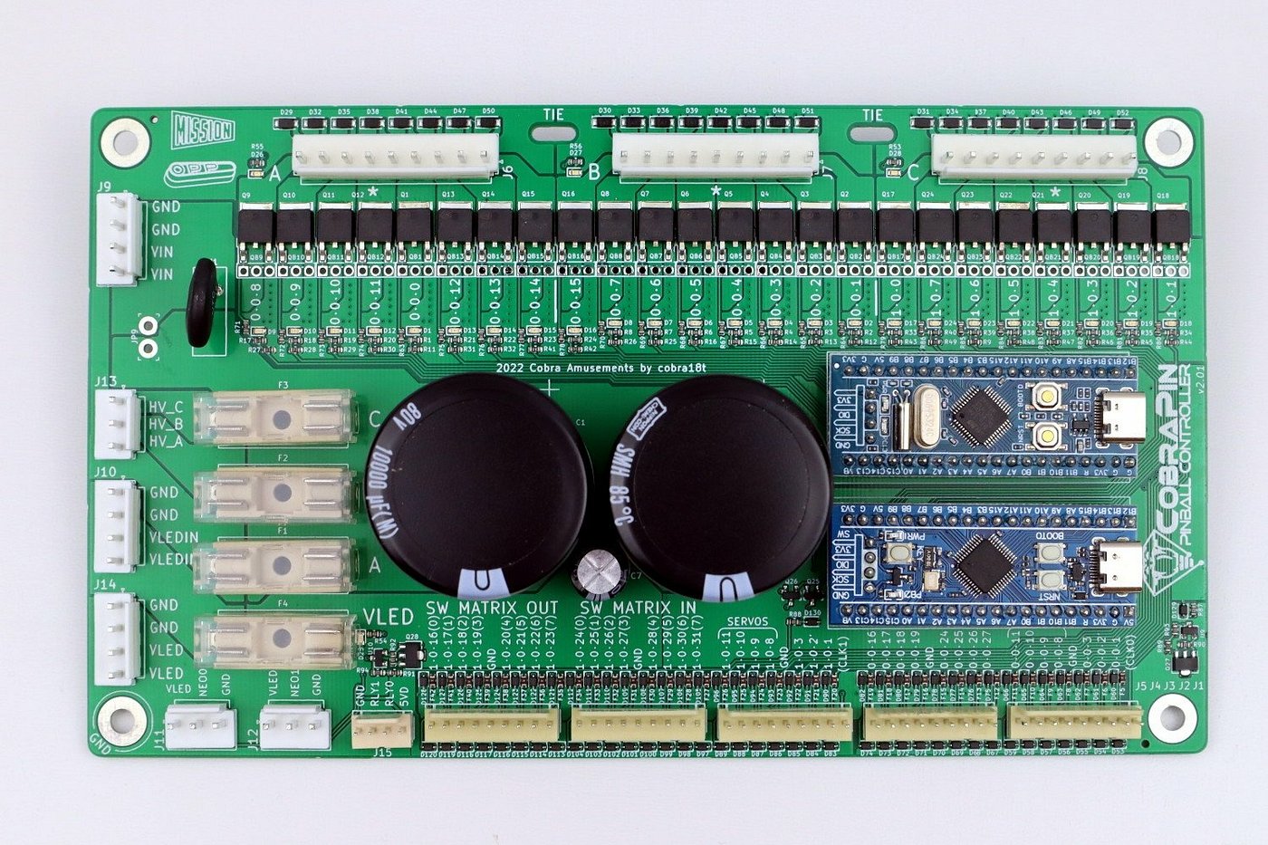
The coil bank's silkscreen prints the MPF number directly next to each pin (visible above:
0-0-8, 0-0-9, 0-0-10, 0-0-11, 0-0-0, 0-0-12, 0-0-13, 0-0-14 for Bank A, continuing
through Banks B/C) — for the solenoid banks, the photo itself is the reference, no lookup table
needed.
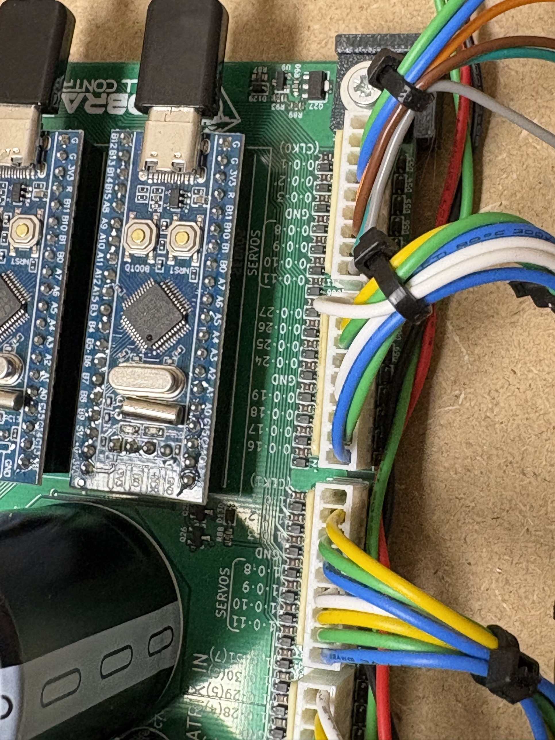
The header connectors (J1-J12, used for switch inputs and the inter-board ribbon chain)
silkscreen the MPF number directly too — confirmed on this cabinet's own board (the close-up
photo above reads 0-0-1, 0-0-2, 0-0-3, GND, 0-0-8-0-0-11 under a "SERVOS" bracket,
then 0-0-27-0-0-24, GND, 0-0-19-0-0-16 — exactly J1 pins 2-9 then J2 pins 1-9 from
the table below, run together on one physical header) and by CobraPin's own
documentation: "The switch inputs are labeled in silkscreen with the MPF compatible numbers"
(same for coil outputs) — see cobrapin-official-wiki in docs/references/. An earlier version
of this doc claimed the opposite for these connectors specifically; that was wrong. The table
below (matching the silkscreen 1:1) is still useful as a compact reference and for the STM32/pin
detail the silkscreen doesn't show:
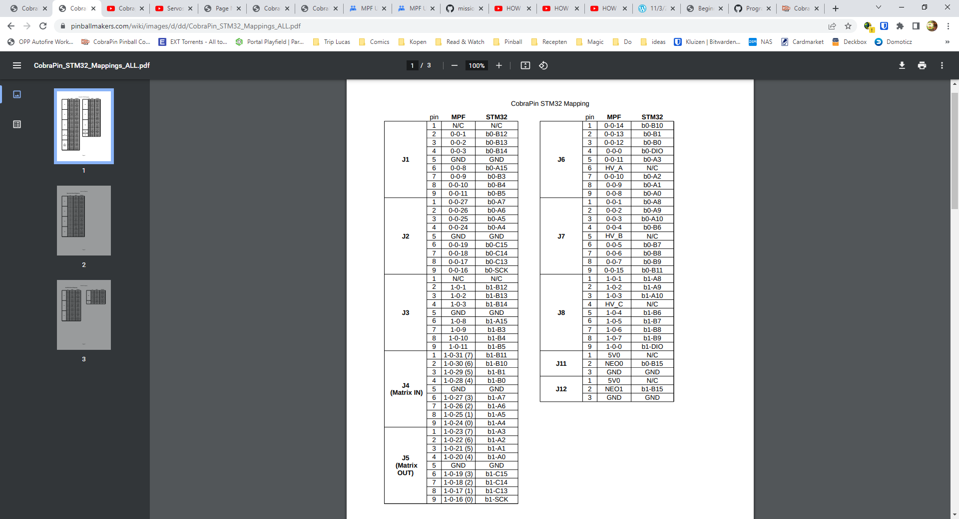
¶ CobraPin STM32 connector mapping
Source: CobraPin_STM32_Mappings_ALL.pdf, pinballmakers.com (embedded in board Overviews.xlsx's
Cobrapin - Doc sheet). chain0-0x20 = b0-* pins below, chain1-0x20 = b1-* pins.
| Connector | Pin | MPF number | STM32 pin |
|---|---|---|---|
| J1 | 1 | N/C | N/C |
| J1 | 2 | 0-0-1 |
b0-B12 |
| J1 | 3 | 0-0-2 |
b0-B13 |
| J1 | 4 | 0-0-3 |
b0-B14 |
| J1 | 5 | GND | GND |
| J1 | 6 | 0-0-8 |
b0-A15 |
| J1 | 7 | 0-0-9 |
b0-B3 |
| J1 | 8 | 0-0-10 |
b0-B4 |
| J1 | 9 | 0-0-11 |
b0-B5 |
| J2 | 1 | 0-0-27 |
b0-A7 |
| J2 | 2 | 0-0-26 |
b0-A6 |
| J2 | 3 | 0-0-25 |
b0-A5 |
| J2 | 4 | 0-0-24 |
b0-A4 |
| J2 | 5 | GND | GND |
| J2 | 6 | 0-0-19 |
b0-C15 |
| J2 | 7 | 0-0-18 |
b0-C14 |
| J2 | 8 | 0-0-17 |
b0-C13 |
| J2 | 9 | 0-0-16 |
b0-SCK |
| J3 | 1 | N/C | N/C |
| J3 | 2 | 1-0-1 |
b1-B12 |
| J3 | 3 | 1-0-2 |
b1-B13 |
| J3 | 4 | 1-0-3 |
b1-B14 |
| J3 | 5 | GND | GND |
| J3 | 6 | 1-0-8 |
b1-A15 |
| J3 | 7 | 1-0-9 |
b1-B3 |
| J3 | 8 | 1-0-10 |
b1-B4 |
| J3 | 9 | 1-0-11 |
b1-B5 |
| J4 (Matrix IN) | 1 | 1-0-31 (7) |
b1-B11 |
| J4 (Matrix IN) | 2 | 1-0-30 (6) |
b1-B10 |
| J4 (Matrix IN) | 3 | 1-0-29 (5) |
b1-B1 |
| J4 (Matrix IN) | 4 | 1-0-28 (4) |
b1-B0 |
| J4 (Matrix IN) | 5 | GND | GND |
| J4 (Matrix IN) | 6 | 1-0-27 (3) |
b1-A7 |
| J4 (Matrix IN) | 7 | 1-0-26 (2) |
b1-A6 |
| J4 (Matrix IN) | 8 | 1-0-25 (1) |
b1-A5 |
| J4 (Matrix IN) | 9 | 1-0-24 (0) |
b1-A4 |
| J5 (Matrix OUT) | 1 | 1-0-23 (7) |
b1-A3 |
| J5 (Matrix OUT) | 2 | 1-0-22 (6) |
b1-A2 |
| J5 (Matrix OUT) | 3 | 1-0-21 (5) |
b1-A1 |
| J5 (Matrix OUT) | 4 | 1-0-20 (4) |
b1-A0 |
| J5 (Matrix OUT) | 5 | GND | GND |
| J5 (Matrix OUT) | 6 | 1-0-19 (3) |
b1-C15 |
| J5 (Matrix OUT) | 7 | 1-0-18 (2) |
b1-C14 |
| J5 (Matrix OUT) | 8 | 1-0-17 (1) |
b1-C13 |
| J5 (Matrix OUT) | 9 | 1-0-16 (0) |
b1-SCK |
| J6 | 1 | 0-0-14 |
b0-B10 |
| J6 | 2 | 0-0-13 |
b0-B1 |
| J6 | 3 | 0-0-12 |
b0-B0 |
| J6 | 4 | 0-0-0 |
b0-DIO |
| J6 | 5 | 0-0-11 |
b0-A3 |
| J6 | 6 | HV_A | N/C |
| J6 | 7 | 0-0-10 |
b0-A2 |
| J6 | 8 | 0-0-9 |
b0-A1 |
| J6 | 9 | 0-0-8 |
b0-A0 |
| J7 | 1 | 0-0-1 |
b0-A8 |
| J7 | 2 | 0-0-2 |
b0-A9 |
| J7 | 3 | 0-0-3 |
b0-A10 |
| J7 | 4 | 0-0-4 |
b0-B6 |
| J7 | 5 | HV_B | N/C |
| J7 | 6 | 0-0-5 |
b0-B7 |
| J7 | 7 | 0-0-6 |
b0-B8 |
| J7 | 8 | 0-0-7 |
b0-B9 |
| J7 | 9 | 0-0-15 |
b0-B11 |
| J8 | 1 | 1-0-1 |
b1-A8 |
| J8 | 2 | 1-0-2 |
b1-A9 |
| J8 | 3 | 1-0-3 |
b1-A10 |
| J8 | 4 | HV_C | N/C |
| J8 | 5 | 1-0-4 |
b1-B6 |
| J8 | 6 | 1-0-5 |
b1-B7 |
| J8 | 7 | 1-0-6 |
b1-B8 |
| J8 | 8 | 1-0-7 |
b1-B9 |
| J8 | 9 | 1-0-0 |
b1-DIO |
| J11 | 1 | 5V0 | N/C |
| J11 | 2 | NEO0 | b0-B15 |
| J11 | 3 | GND | GND |
| J12 | 1 | 5V0 | N/C |
| J12 | 2 | NEO1 | b1-B15 |
| J12 | 3 | GND | GND |
¶ PSOC4200 (red boards, chain 2)
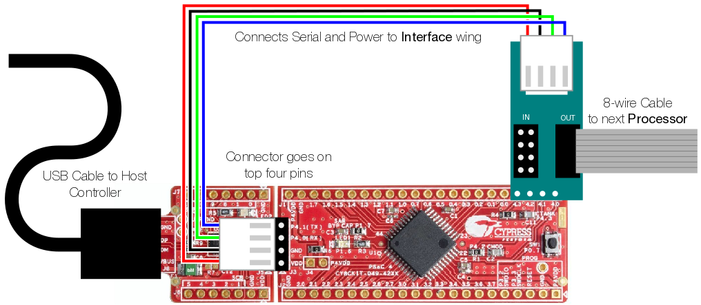
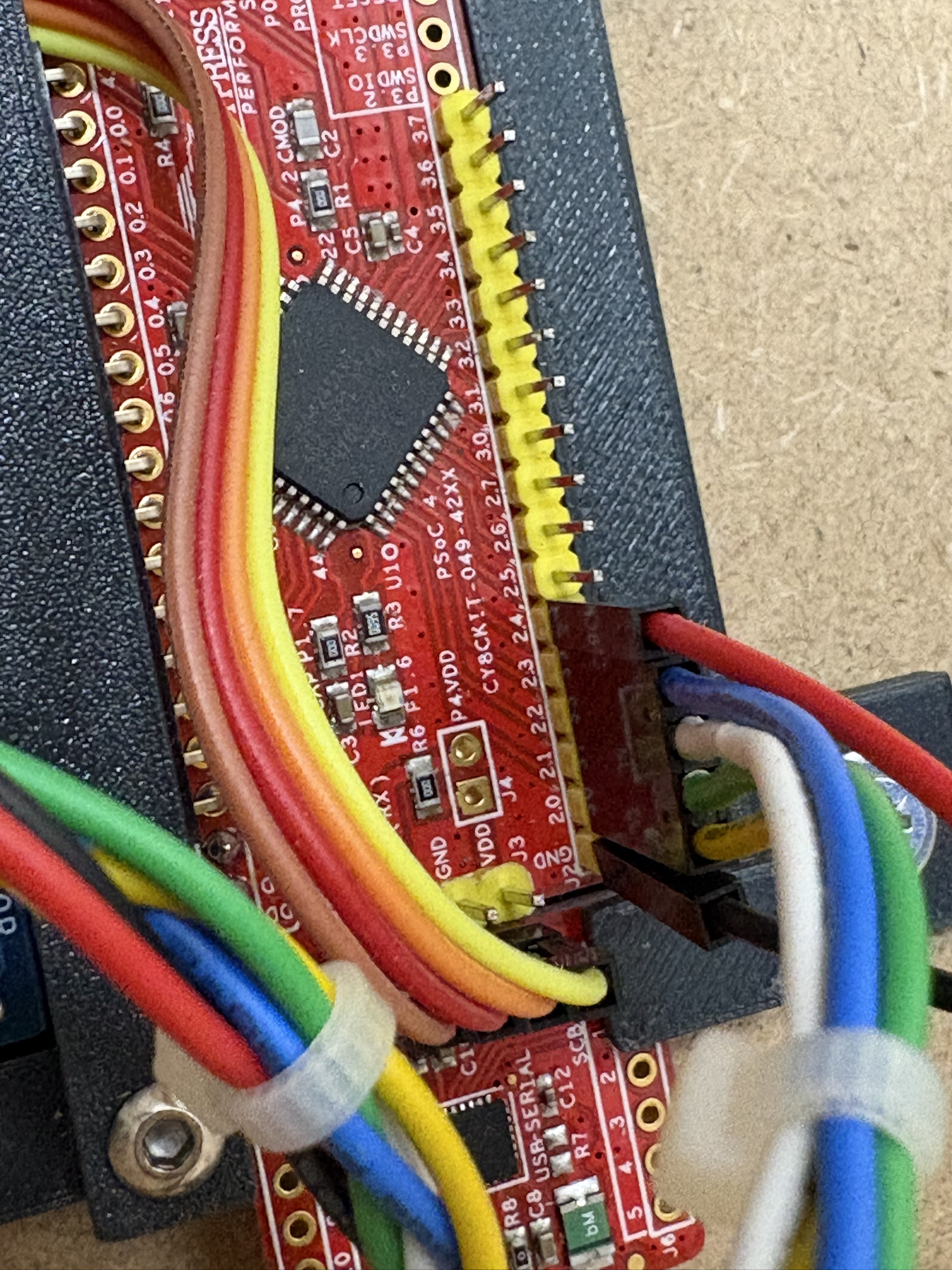
Unlike CobraPin, the red board's silkscreen only prints the raw physical PSoC4200 pin label
(P0.0-P0.7, P1.0-P1.7, P2.0-P2.7, P3.0-P3.7) — never the MPF number directly. The
tables below (extracted from board Overviews.xlsx's PSOC4200 - Game Function sheet) give the
physical-pin ↔ MPF-number mapping for each of the four boards. "Game-function name (historical)"
is this sheet's own original device naming — cross-check against components.yaml for the current
name/status, since names and assignments have both drifted since this sheet was last updated.
¶ PSOC4200 red-board per-pin reference
Each board gets a generated visual (silkscreen pin / MPF number / device name, color-coded by
function) followed by the same data as a table — the visual for a quick glance while looking at
the physical board, the table for searching/scanning.
¶ chain2-0x20

Historical, like the table below: the device names are the xlsx plan's (e.g. s_bottomlane5,
now s-button). Today's pins: docs/wiring-guide.md.
| Physical pin | Pin index | MPF number | Function | Game-function name (historical) |
|---|---|---|---|---|
| 0.0 | 0 | 2-0-0 |
auto fire | s_sling_right |
| 0.1 | 1 | 2-0-1 |
auto fire | s_sling_left |
| 0.2 | 2 | 2-0-2 |
auto fire | #NA |
| 0.3 | 3 | 2-0-3 |
auto fire | #NA |
| 0.4 | 0 | 2-0-0 |
coil | c_sling_right |
| 0.5 | 1 | 2-0-1 |
coil | c_sling_left |
| 0.6 | 2 | 2-0-2 |
coil | c_plunger |
| 0.7 | 3 | 2-0-3 |
coil | c_trough_eject |
| 1.0 | 8 | 2-0-8 |
auto fire | s_popbumper_1 |
| 1.1 | 9 | 2-0-9 |
auto fire | s_popbumper_2 |
| 1.2 | 10 | 2-0-10 |
auto fire | s_popbumper_3 |
| 1.3 | 11 | 2-0-11 |
auto fire | #NA |
| 1.4 | 4 | 2-0-4 |
coil | c_popbumper_1 |
| 1.5 | 5 | 2-0-5 |
coil | c_popbumper_2 |
| 1.6 | 6 | 2-0-6 |
coil | c_popbumper_3 |
| 1.7 | 7 | 2-0-7 |
coil | c_drop |
| 3.7 | 16 | 2-0-16 |
switch | plunger_lane |
| 3.6 | 17 | 2-0-17 |
switch | start |
| 3.5 | 18 | 2-0-18 |
switch | launch |
| 3.4 | 19 | 2-0-19 |
switch | s_toplane1 |
| 3.3 | 20 | 2-0-20 |
switch | s_toplane2 |
| 3.2 | 21 | 2-0-21 |
switch | s_toplane3 |
| 3.1 | 22 | 2-0-22 |
switch | s_bottomlane1 |
| 3.0 | 23 | 2-0-23 |
switch | s_bottomlane2 |
| 2.7 | 24 | 2-0-24 |
switch | s_bottomlane3 |
| 2.6 | 25 | 2-0-25 |
switch | s_bottomlane4 |
| 2.5 | 26 | 2-0-26 |
switch | s_bottomlane5 - not on field |
| 2.4 | 27 | 2-0-27 |
switch | s_orbit-r |
| 2.3 | 28 | 2-0-28 |
switch | s_orbit-l |
| 2.2 | 29 | 2-0-29 |
switch | s-target-e1 |
| 2.1 | 30 | 2-0-30 |
switch | s-target-e2 |
| 2.0 | 31 | 2-0-31 |
switch | s-button |
¶ chain2-0x21

| Physical pin | Pin index | MPF number | Function | Game-function name (historical) |
|---|---|---|---|---|
| 0.0 | 0 | 2-1-0 |
auto fire | (empty) |
| 0.1 | 1 | 2-1-1 |
auto fire | (empty) |
| 0.2 | 2 | 2-1-2 |
auto fire | (empty) |
| 0.3 | 3 | 2-1-3 |
auto fire | (empty) |
| 0.4 | 0 | 2-1-0 |
coil | (empty) |
| 0.5 | 1 | 2-1-1 |
coil | (empty) |
| 0.6 | 2 | 2-1-2 |
coil | (empty) |
| 0.7 | 3 | 2-1-3 |
coil | (empty) |
| 1.0 | 8 | 2-1-8 |
auto fire | (empty) |
| 1.1 | 9 | 2-1-9 |
auto fire | (empty) |
| 1.2 | 10 | 2-1-10 |
auto fire | (empty) |
| 1.3 | 11 | 2-1-11 |
auto fire | (empty) |
| 1.4 | 4 | 2-1-4 |
coil | (empty) |
| 1.5 | 5 | 2-1-5 |
coil | (empty) |
| 1.6 | 6 | 2-1-6 |
coil | (empty) |
| 1.7 | 7 | 2-1-7 |
coil | (empty) |
| 3.7 | 16 | 2-1-16 |
switch | s_trough1 |
| 3.6 | 17 | 2-1-17 |
switch | s_trough2 |
| 3.5 | 18 | 2-1-18 |
switch | s_trough3 |
| 3.4 | 19 | 2-1-19 |
switch | s_trough4 |
| 3.3 | 20 | 2-1-20 |
switch | s_trough5 |
| 3.2 | 21 | 2-1-21 |
switch | s_trough6 |
| 3.1 | 22 | 2-1-22 |
switch | s_trough_jam |
| 3.0 | 23 | 2-1-23 |
switch | s_drop1 |
| 2.7 | 24 | 2-1-24 |
switch | s_drop2 |
| 2.6 | 25 | 2-1-25 |
switch | s_drop3 |
| 2.5 | 26 | 2-1-26 |
switch | s_vukmid |
| 2.4 | 27 | 2-1-27 |
switch | s_vuktop |
| 2.3 | 28 | 2-1-28 |
switch | s-orbit-top |
| 2.2 | 29 | 2-1-29 |
switch | s-portal-r |
| 2.1 | 30 | 2-1-30 |
switch | s-dropper |
| 2.0 | 31 | 2-1-31 |
switch | s-exit-success |
¶ chain2-0x22 (also carries the incandescent wing)

| Physical pin | Pin index | MPF number | Function |
|---|---|---|---|
| 0.0 | 0 | 2-2-0 |
light |
| 0.1 | 1 | 2-2-1 |
light |
| 0.2 | 2 | 2-2-2 |
light |
| 0.3 | 3 | 2-2-3 |
light |
| 0.4 | 4 | 2-2-4 |
light |
| 0.5 | 5 | 2-2-5 |
light |
| 0.6 | 6 | 2-2-6 |
light |
| 0.7 | 7 | 2-2-7 |
light |
| 1.0 | 8 | 2-2-8 |
light |
| 1.1 | 9 | 2-2-9 |
light |
| 1.2 | 10 | 2-2-10 |
light |
| 1.3 | 11 | 2-2-11 |
light |
| 1.4 | 12 | 2-2-12 |
light |
| 1.5 | 13 | 2-2-13 |
light |
| 1.6 | 14 | 2-2-14 |
light |
| 1.7 | 15 | 2-2-15 |
light |
| 3.7-2.0 | 16-31 | 2-2-16 … 2-2-31 |
not used (per this historical sheet — double-check against current components.yaml before assuming still true) |
¶ chain2-0x23

| Physical pin | Pin index | MPF number | Function | Game-function name (historical) |
|---|---|---|---|---|
| 0.0 | 0 | 2-3-0 |
switch | s-target-r1 |
| 0.1 | 1 | 2-3-1 |
switch | s-target-r2 |
| 0.2 | 2 | 2-3-2 |
switch | s-target-m1 |
| 0.3 | 3 | 2-3-3 |
switch | s-target-m2 |
| 0.4 | 4 | 2-3-4 |
switch | s-target-m3 |
| 0.5 | 5 | 2-3-5 |
switch | s-target-m4 |
| 0.6 | 6 | 2-3-6 |
switch | s-target-l1 |
| 0.7 | 7 | 2-3-7 |
switch | s-ramp-r1 |
| 1.0 | 8 | 2-3-8 |
switch | s-ramp-l1 |
| 1.1 | 9 | 2-3-9 |
switch | s-ramp-r2 |
| 1.2 | 10 | 2-3-10 |
switch | s-ramp-l2 |
| 1.3 | 11 | 2-3-11 |
switch | s-aerial |
| 1.4 | 12 | 2-3-12 |
switch | s-portal-m |
| 1.5 | 13 | 2-3-13 |
switch | s-insinerator |
| 1.6 | 14 | 2-3-14 |
switch | (unlabeled in sheet) |
| 1.7 | 15 | 2-3-15 |
switch | (unlabeled in sheet) |
| 3.7-2.0 | 16-31 | 2-3-16 … 2-3-31 |
switch | (unlabeled in sheet) |
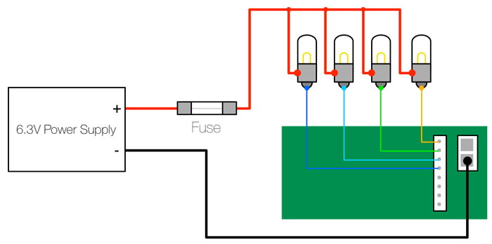
¶ Generic OPP wing wiring (any red board)
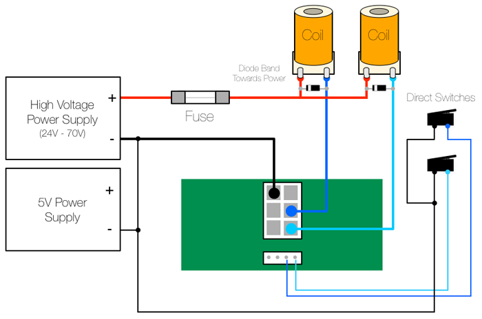
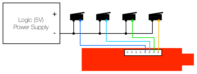
Power/wire-color reference for the three wing types, independent of which specific board — from
board Overviews.xlsx's Coil/Switch/Incand sheets:
¶ Sources
board Overviews.xlsx(repo root) —Cobrapin - Doc,Cobrapin - Game Funtion,
PSOC4200 - Doc,PSOC4200 - Config,PSOC4200 - Game Function,Coil,Switch,Incand
sheets, and their embedded images (extracted intodocs/board-photos/for this doc — the xlsx
itself is still never auto-parsed for live status, pertools/hw_console/README.md, this was a
one-time manual extraction).docs/opp-hardware-reference.md— the board-priority policy and pairing rules this reference
data feeds into.